
full bridge HV buck smps EasyEDA open source hardware lab
This method of feedback maintains the electrical isolation between the primary and secondary sections of the circuit. The controller provides the PWM drive signal to the power switch M1, STMicroelectronics ' STB21N90K5 900 volt, 18.5 amp, MOSFET. The design tool also helps select or design the flyback transformer.
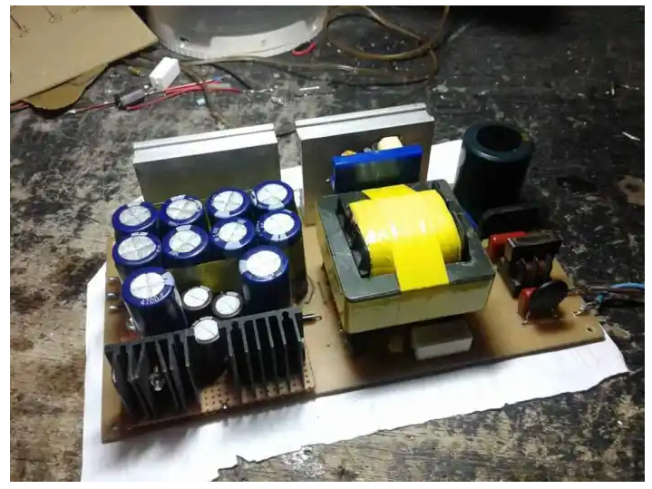
Cara Membuat SMPS Dari Gacun CT Untuk Power Amplifier Yang Stabil
SMPS FULLBRIDGE PFCF OLD SMPS FULLBRIDGE PFC VERSI OLD Bagi yg mau mencoba merakitntya file sprint layout nya bisa di download disini. http://fumacrom.com/3oxJA f. NEW SMPS HALFBRIDGE+OCP BY CKM TRONIK SMPS HalfBridge 2.5kva dengan mengunakan osc SOS.dan sudah saya lenkapi dengan OCP+OVP dan SOFTSTART. 1.OCP..pungsinya jika terjadi shor.

Skema Switching SMPS LG CRT Monitor 15 Inchi Tutorial, Desain & Hoby
This DC-DC converter proves the feasibility of HB LLC as a high-efficiency topology for a 3.3 kW converter, at the level of full-bridge LLC or dual-stage LLC when combined with the latest best-in-class Infineon devices with their benchmark low R DS(on) and low parasitics.

Pcb SMPS Full Bridge Pfc
Switching Mode Power Supply (SMPS) has become a standard type of power supply unit for electronic devices because of their high efficiency, low cost and high power density. The following image shows an SMPS unit from an old desktop computer. This particular SMPS is rated for 90W of power. Linear Regulator vs. SMPS What is the purpose of SMPS?
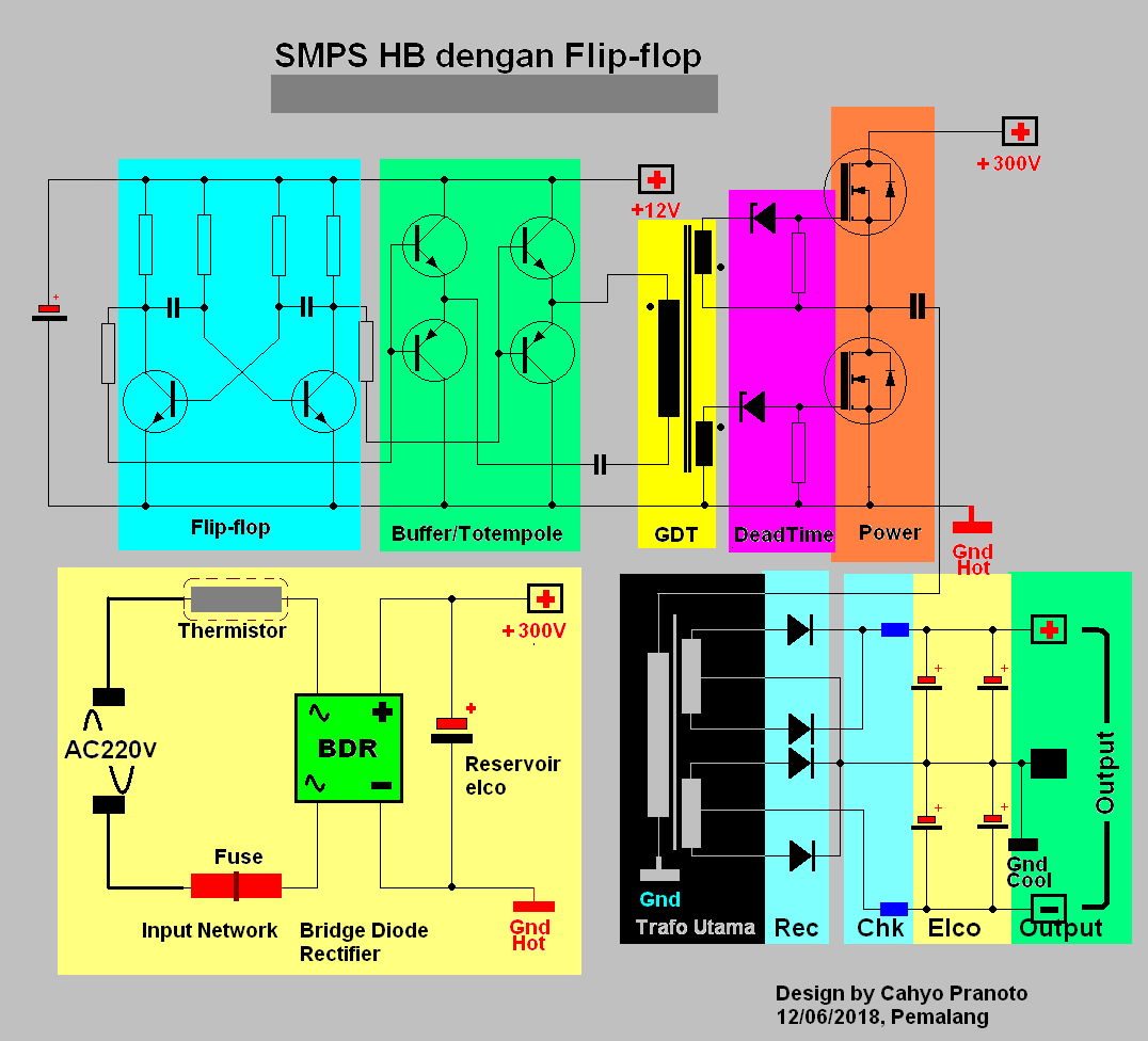
Skema Smps Hb Sederhana
We're building another Full Bridge converter… but this one is different! Designing for a wide input range is not an easy task, but that's the challenge we're.

Audio Kreatif SKEMA SMPS 1200WATT
supplies. It also provides real SMPS examples, and identifies several application notes and additional design resources available from ON Semiconductor, as well as helpful books available from various publishers and useful web sites for those who are experts and want to increase their expertise.

smps full bridge sos EasyEDA open source hardware lab
1. For PWM frequency adjustment 30-130kHz 2. Duty cycle adjustment 30-40% Low Side gate adjustment 3. Overcurrent adjustment sensitivity 4. Aux DC out adjustment PWM Gate signal at 82kHz and Duty Cycle 38.1% Transformer Ferrite EE55/28/21 Np Working Frequency 30-40kHz = 18 turns 40-50kHz = 16 turns 50-60kHz = 15 turns 60-80kHz = 14 turns

ADE7953 connection in non isolated SMPS, full bridge rectifier Q&A
This paper presents a high-efficiency AC-DC switch-mode power supply (SMPS) using the full-bridge converter circuits. The proposed converter utilizes three full-bridge converter circuits: two full-bridge diode converter circuits and one full-bridge MOSFET converter circuit. The two full-bridge converters are utilized at the primary AC input and.

Tahmid's blog SMPS TopoMagic
the asymmetrical half bridge needs a floating gate drive for the high side switch. Figure 10: Half bridge asymmetrical forward converter * Power switch: V CEV or V DSS ≥ V inmax * Rectifiers: FORWARD D1: V inmax (V out + V F) V inmin. δ max V RRM ≥ I F(av) ≥I out.δ max FREEWHEELING D2: V RRM ≥V inmax (V out + V F) I F(av) ≥I out 1.2.
Layout Smps Full Bridge Saga Now
Typical full bridge driver connection diagram. Decades of application expertise and technology development at both Infineon and International Rectifier have produced a portfolio of gate driver ICs for use with silicon and wide-bandgap power devices, such as MOSFETs, discrete IGBTs, IGBT modules, SiC MOSFETs and GaN HEMTs. We offer excellent.

Full Bridge Smps Circuit Diagram
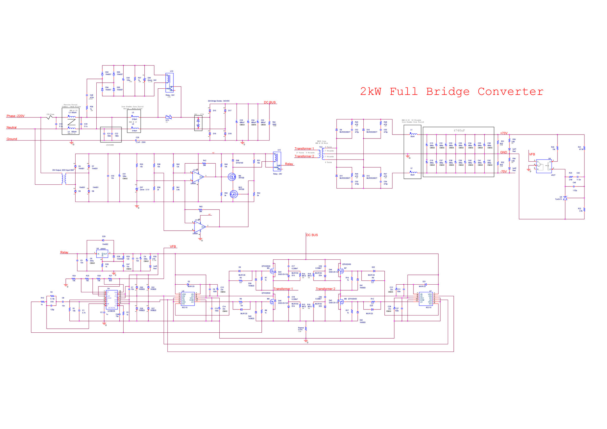
FULL-BRIDGE-SMPS Last Updated: Jun 8, 2023 The full-bridge DC-DC switch mode power supply reference design is based on V series MCUs and intended to provide the example of power conversion applications. The full-bridge DC-DC converter is a transformer-isolated buck converter. The full-bridge topology contains full-bridge

Smps Full Bridge fishfasr
The flyback design is a switched-mode power supply (SMPS) that's been used for 70+ years and still going strong. This supply—also called a power converter—has two distinct operating phases.

SKEMA SMPS BERBAGI ITU INDAH YouTube
2013-11-15 6:45 pm. #1. I am working on a full bridge boost converter capable of putting 900 watts into a load. This is based upon TL494 pwm generator from Texas instruments. TL494 is made to work in complementary output logic. But there is a little problem with the mosfet deriving stage. I am using the standard circuit given in the datasheet.
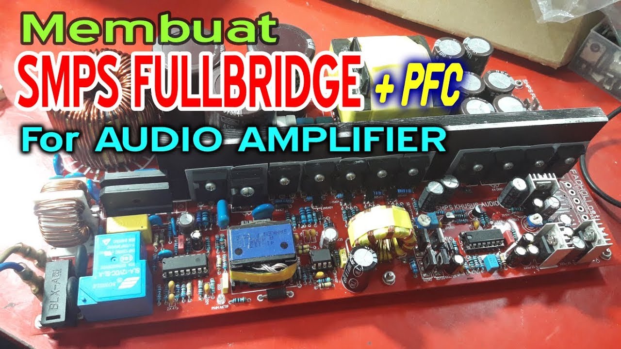
Cara Membuat SMPS FULLBRIDGE PFC YouTube
Read about SG3525 SMPS Regulator IC. Some Notes Related to the Project In main circuit do not link different grounds. Main circuit can be used both for 110 AC and 230 AC Ferrites are partial conductors use proper insulation before winding. For main transformer TRX2 use split bobbin for good/safe isolation.
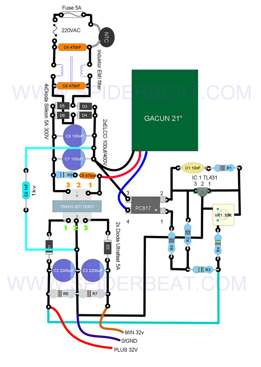
Skema SMPS Gacun Lengkap dengan Cara Membuatnya
FULL-BRIDGE-SMPS Receive alerts. The full-bridge DC-DC switch mode power supply reference design is based on V series MCUs and intended to provide the example of power conversion applications. The full-bridge DC-DC converter is a transformer-isolated buck converter. The full-bridge topology contains full-bridge inverter block, transformer.

sg3525 full bridge EasyEDA open source hardware lab
The crucial hurdle in a full bridge or a H-bridge design is the incorporation of 4 N-channel mosfet full bridge topology, which in turn demands the incorporation of a bootstrap mechanism for the high side mosfets. What's Bootstrapping